DESIGN OF
CORE AND FILTER IN EARTH AND ROCKFILL DAMS
1.0 DAMS AND THEIR DESIGN PHILOSOPHY
1.1 Role Played By Dams & Reservoirs
Dams have been
built across rivers by mankind right from the dawn of civilization for storing
the river flow during rainy season and releasing it during the remaining part
of year for either domestic use or for irrigation. Flood control has been
another important function of these dams. While releasing water from the
storages, hydroelectric energy is also generated. With the growth of population all these
functions of dams and storages have assumed great significance and hence every
civilization has tried to keep pace with the needs of the society for food,
energy, fibre and well being through this activity of water resources
development.
1.2 Inputs For Safe Design
Dams constitute
perhaps the largest and the most complex of structures being built by civil
engineers. Basic input of water is
dependent on nature, so also the river course, its history, its underlying
strata and its stability. Assessment of
the variability of these natural phenomenon and providing for it in the design
of a dam, has been an important challenge for the dam builders. The dams are built to last from 100 to 300
years depending upon merits of each case.
During their service life, they are designed to withstand all the
possible destabilizing forces with a certain factor of safety which has been an
indicator of a factor of ignorance or lack of knowledge of various response
processes of materials used in construction, the stresses caused, the stains
experienced and finally the failure mechanism.
ALSO READ: DESIGN PRINCIPLES OF EARTH DAM
ALSO READ: FOUNDATION TREATMENT FOR DAMS
1.3 Design Constants
The destabilizing
forces themselves are associated with a significant natural variability. Assessment of the range of these forces
likely to affect a dam stability during its lifetime and then ascribing a
design value for such forces has been and will continue to be a matter of study
and concern for the designers. Every
design or construction engineer cannot study these processes for every dam and
hence standards or codes of design and construction practice are laid down and
updated as information and knowledge grows
Assistance of scientists working in fields such as Hydrometeorology,
Geology, Geophysics, Geomorphology, Seismology in assessing the likely
parameters of these forces is taken, the information collected is processed as
per standards and design constants worked out.
Large dams store
very large volumes of water. Design of
such dams, therefore, has to be extra safe so that there is a minimum
probability of their failure and consequent rapid or sudden release of storage
which can cause disproportionate flooding and losses to the human habitats in
the downstream. Very stringent codes are
laid down for this purpose. In case of
inflow into a reservoir, for instance, a conceptual Probable Maximum Flood
(PMF) is determined by following special analytical procedures. If the reservoir and the spillway caters to a
properly determined outflow on the basis of such inflow, the dam
would be hydrologically safe. In similar manner, geotechnical properties of
foundation material or construction material can be determined and design
constants worked out so that structural design based on them yields a safe
structural construction. Statistically
speaking, the design constants should cover the probability of occurrence of
forces expected during the lifetime of the structure under design.
1.4 Design Philosophy
The codes of
practice invariably lag the strata or knowledge or state of Research &
Development (R&D). In fact
codification follows verification of generated knowledge and its global acceptance.
Codes, therefore, tend to remain conservative and normally incorporate a
higher factor of safety and hence perhaps yield structures with larger
dimension and/or with higher costs.
There is yet another aspect of design philosophy which is not very explicitly
understood nor adequately explained. It
pertain to the various stages of design for complex structures like dams viz.
conceptualization, pre-feasibility, feasibility, detailed project report (DPR),
pre-construction, early construction and advanced construction stages.
1.5 Refine The Design As You Build
A designer starts
with broad concept of design parameters in the beginning and goes on refining
his data base and hence the designs, as he proceeds through the various
stages. He assumes for the sake of his
inadequate data base, simplifications or generalizations which obviously
incorporates a large factor safety in initial stages. As the passes through successive stages, his
data base proves, better and more accurate data base emerges; the range of design constants narrows down
and factor of safety reduces.
Generally, the outer dimensions of a structure do not necessarily get
modified; but components, zones or internal
arrangements of a structure do undergo modification. The structure’s response to the destabilizing
forces is worked out with greater detail and is refined while moving from one
stage to the next stage. Engineers call
this a process which is loosely described as ‘Design as you build’ or ‘Refine the design as you build’ mode. It certainly does not mean inadequacy of
design or does not reflect on ignorance or incompetence of project or design
engineers. However, an inadequate
understanding of this very philosophy is one major factor responsible for much
public criticism of many of our water resources projects.
ALSO READ: FOUNDATION TREATMENT FOR DAMS
2.0 Defensive Measures
International practice recommends deployment of various
defensive measures to provide extra safety in design of high risk rockfill
dams.
- Allow ample freeboard to allow for settlement, slumping
or faul movements.
- Use wide
transition zones of material not vulnerable to cracking.
- Use chimney near
the central portion of embankment.
- Provide ample drainage zones to allow for possible flow
of water through cracks.
- Use wide core
zones of plastic materials not vulnerable to cracking.
- Use a
well-graded filter zone upstream of the core to serve as a crack stopper.
- Provide crest
details which will prevent erosion in the event of overtopping.
- Flare the
embankment core at abutment contacts.
- Locate the core
to minimize the degree of saturation of materials.
- Stabilize slopes
around the reservoir rim to prevent slides into the reservoir.
- Provide special details if danger of fault movement in
foundation exists.
This list should not by any means be considered as
all-inclusive. However, defensive
measures, specially the use of wide filters and transition zones, provide a
major contribution to earthquake-resistant design and should be the first
consideration by the prudent engineer in arriving at a solution to problems
posed by the possibility of earthquake effects.
ALSO READ: FOUNDATION TREATMENT FOR DAMS
3.0 Criteria for Safe Design of Earth/Rock fill Dam
(i) There should
lie no possibility of dam being overtopped by flood water.
(ii) The seepage
line should be well within the downstream face.
(iii) The u/s and d/s slopes should be stable under worst
condition.
(iv) The
foundation shear stresses should be under safe limits.
(v) There should
be no opportunity of free flow of water from u/s to d/s face.
(vi) The dam and
foundation should be safe against piping.
(vii) The U/s face should be properly protected against
wave action and the d/s face
against the action of rain
4.0 DESIGN OF
CORE FOR ROCK FILL DAMS

4.1 Core
4.2 The core provides impermeable barrier within the body
of the dam. Impervious soils are generally suitable for core. However, soils having high compressibility
and liquid limit are not suitable as they are prone to swelling and formation
of cracks.
Soils having organic content are also not suitable. IS:1498-1970 may be referred for suitability of soils for
core. Appendix A gives
recommendations based on
IS:14981970. Recommendations regarding
suitability of soils for construction of
core for earth dams in earthquake zones are given in Appendix B.
4.3 Core may be located either centrally or inclined
upstream. The location will depend
mainly on the availability of materials, topography of site, foundation
conditions, diversions considerations, etc.
The main advantage of a central core is that it provides higher
pressures at the contact between the core and the foundation educing the
possibility of leakage and piping. On
the other hand inclined core reduced the
pore pressures in the downstream part of the dam and thereby increases its safety. It also permits construction of downstream
casing ahead of the core. The section with
inclined core allows the use of relatively large volume of random
material on the downstream.
ALSO READ: FOUNDATION TREATMENT FOR DAMS
4.4. The following practical considerations govern the
thickness of the core:
a) Availability of suitable impervious material; b)
Resistance to piping; c) Permissible seepage through the dam; and d)
Availability of other materials for casing, filter, etc.
However, the minimum top width of the core should be 3.0 m.
4.5 The top level
of the core should be fixed at least 1 metre above the maximum water level to prevent seepage by capillary siphoning.
5.0 Casing
5.1 The function of casing is to impart stability and
protect the core. The relatively
pervious materials, which are not subject to cracking on direct exposure
to atmosphere are suitable for casing. IS:1498-1970 may be referred for suitability of soils for
casing. Appendix A gives recommendations based on IS:1498-1970.
6.0 Special Design Requirements
6.1 In addition to basic design requirements given at 5,
the following special design
requirements, should also be satisfied for both earth and rock fill
dams: a) Control of cracking. b) Stability in earthquake regions, and c)
Stability at junctions.
6.2 Control of Cracking - Cracking of impervious zone
results into a failure of an earth dam by erosion, breaching, etc. Due consideration to cracking phenomenon
shall, therefore, be given in the design of earth dam.
6.3 Reasons of Cracking - Cracking in the core of earth or rockfill dam occurs due to foundation settlement and/or differential movements within the embankment. Differential movements in the embankment take place due to the following reasons:
a) Unsuitable
and/or poorly compacted fill materials, b) Different compressibility and
stress-strain characteristics of the various fill materials, and c) Variation
in thickness of fill over irregularly shaped or steeply inclined abutments.
6.4 .Cracking also develops by tensile strains caused by
various loads, such as dead load of the structure, filling of the reservoir and
seismic forces. Hydraulic fracturing of
the core may also occur when the hydrostatic pressure at a section in the core
exceeds the total minor principal stress at that section.
6.5 Types of Cracks - Cracks may be classified based on
the following factors: a) Mechanism by
which cracks are developed, such as tensile, compressive, shrinkage or
shearing. b) Types of surface with which the cracking is associated, such as
flat or steep. c) Physical process involved, such as moisture or temperature
changes, loading or unloading action and dynamic activity, such as blasting or
earthquakes.
6.6 Tensile stresses produce cracks on flat surface by
capillary action in the moisture range
just below saturation. Tensile stress
steep slope category cracks are associated with slumping in poorly consolidated
materials.
6.7 Shrinkage
cracks are produced by wetting and drying
action in the moisture range of plasticity index.
6.8
Compression cracks on flat
surface are produced by
an abrupt change
in moisture followed by
substantial consolidation and cracking around the periphery of the affected
area.
6.9 Cracking
associated with shearing is commonly associated with steep slopes. There are two conditions in
this category. One is
differential settlement which involves
a limited range of motion and the other is a slide failure which may involve
any amount of motion. The differential
settlement condition commonly involves a structure extending over two or more
kinds of foundation with differing compressive characteristics or a
differential loading condition on a single kind of foundation material.
6.10 Slide
failures may be associated with loading ,unloading or moisture change, the distinguishing characteristics is the
potential for continued movement.
6.11 Importance
of Cracks - Relative importance of each type of crack category or group is given at 3.1.3.1 to 3.1.3.3.
6.11.1 Where permeability
and possible erosion
are of primary
concern, the tension group is potentially the most serous. In this group, the cracks are open and
although usually only superficial, those associated with steep slopes may
extend to depths comparable to the size of structure involved.
Though the development of this type of cracking is from
the surface, it may persist, although deeply buried, where eventually it may
contribute to unsatisfactory seepage action.
6.11.2 Where
maintenance of position is a prime structural requirement the compression type of cracking is the most important
because it is probable that when this type of cracking appears the settlement
has already completed.
6.11.3 Shearing
cracks are identified primarily by displacement between the two sides and a tearing configuration. Unlike tension or compression cracking,
shearing cracks commonly occur early in the failure action and further movement
can be expected after the first cracking shows up.
6.12 Measures for Control of Cracking - Following
measures are recommended for control of
cracking:
a) Use of plastic clay core and rolling the core material
at slightly more than optimum moisture content.
In case of less plastic clay, 2 to 5 percent bentonite of 200 to 300
liquid limit may be mixed to increase the plasticity. b) Use of wider core to
reduce the possibility of transverse or horizontal cracks extending through it. c) Careful selection of fill materials to
reduce the differential movement. To restrict the rockfill in lightly loaded
outer casings and to use well graded
materials in the inner casings on either side of the core. d) Wide
transition zones of properly graded filters of adequate width for handling
drainage, if cracks develop. e) Special treatment, such as preloading,
pre-saturation, removal of weak material etc., to the foundation and abutment,
if warranted. f) Delaying placement of core material in the crack region till
most of the settlement takes place. g) Arching the dam horizontally between
steep abutments. h) Flattening the downstream slope or increase slope stability
in the event of saturation from crack leakage. i) Cutting back of steep abutment
slopes.
ALSO READ: FOUNDATION TREATMENT FOR DAMS
7.0 Foundation Treatment Below Core :
The core contact area includes the foundation contact for
the entire base width of the impervious core, the upstream and the
downstream filter zones, transitions and the downstream drain. This area is the most important and critical
in the foundation treatment of earth-core rockfill dams. The controlling
factors are:
1. The rock under the core, including the infilling
material in faults and joints, must be non-erodible and must be protected from erosion under seepage
gradients that will develop under the core. 2. Materials of the core must be
prevented from moving down into the foundations. 3. The contact between the
core and the foundation rock surface must remain intact despite distortions that
might occur in the dam due to its weight and reservoir loading.
The primary hazards to a high embankment dam are cracking
within the corecaused by unequal settlement and the development of seepage
channels along the contact of the impervious core with the foundation and
abutment rock. Either of these defects could lead to failure of the dam. It must therefore be ensured that the
foundation in the core-contact area consists of sound and hard rock
reasonablyfree from joints and fissures which could be the cause of internal
erosion.
These objectives are achieved by excavation of the
uppermost weathered rock zones to the level of sound rock and by consolidation
grouting to reduce the permeability of the rock under the excavated
surface. Jointed rock is an acceptable
foundation, provided the joints do not contain soft materials or clays to an extent that could endanger the stability
of the rock.
8.0 Suitability of Soils for Construction of Earth Dam
|
Sl.No |
Suitability |
Zoned
Earthdam |
|
|
|
|
Impervious Core |
Pervious Casting
|
|
1 |
Very suitable |
GC |
SW, GW |
|
2 |
Suitable |
CL, CI |
GM |
|
3 |
Fairly suitable
|
GM, GC, SM, SC, CH |
SP, GP |
|
4 |
Poor |
ML. MI, MH |
- |
|
5 |
Not suitable |
OL, OI, OH |
- |
9.0 Suitability of Soils for Construction of Core of
Earth Dam in Earthquake Zones
|
Sl.No |
Suitability |
Type of Soil |
|
1 |
Very Good |
Very well graded coarse mixtures of sand, gravel and fines., D85 coarser than 50mm, D50
coarser than 6 mm. If fines are cohesionless,
not more than 20 percent finer than 75 micron IS Sieve. |
|
2 |
Good |
a) Well graded mixture of sand, gravel and clayey fines, D85 coarser than 25 mm Fines consisting of inorganic clay (CL with plasticity
index greater than 12). b) Highly plastic tough clay (CH with plasticity index greater than 20). |
|
3 |
Fair |
Fair a) Fairly
well graded, gravelly, medium to coarse
sand with cohesionless fines, D85
coarser than 19 mm, D50 between 0.5 mm and 3.0 mm. Not more than 25
percent finer than 75 micron IS sieve. b) Clay of medium plasticity (CL with
plasticity index greater than 12). |
|
4 |
Poor |
) Clay of low plasticity (CL and CL-ML) with
little coarse fraction.
Plasticity index between 5 and 8.
Liquid limit greater than 25. Liquid limit greater than 25. b) Silts of medium to high plasticity (ML or MH) with little coarse fraction. Plasticity index greater than 10. c) Medium sand
with cohesion less fines. |
|
5 |
Very Poor |
a) Fine, uniform, cohesion less silty sand, D85 finer than 0.3 mm. b) Silt from medium plasticity to cohesionless
(ML) Plasticity index less
than 10. |
10.0 Location of Core in Dam Section and Type of Core
The core can be
located in one of the following three positions:
(1) central,
(2) moderately
slanting or
(3) slanting.
The central location need not be exactly symmetrical: cores with a steeper downstream
slope and flatter upstream slope, or
even with a slight slant in the
upstream direction would still have
characteristics of central cores.
When the downstream face of the core has an upstream
slant of 0.5 H : 1 V or more, the core
may be considered as moderately slanting.
A truly slanting
core would be such that the downstream zone has a self-supporting slope, i.e., 1.25 H:1 V or more,; such a core is
almost always associated with a rockfill
dam in which the main mass of rockfill downstream of the core can be
placed independently by dumping or in thick layers and the placement of filter
zones, core and upstream pervious zone
taken up later. Even with a moderately slanting core, if the downstream rockfill zone is
substantial, it is possible to carry out a
portion of the work ahead of core
placement.
The relative advantages and disadvantages of vertical and
sloping cores are discussed below:
ALSO READ: FOUNDATION TREATMENT FOR DAMS
10.1 Slanting Core
Advantages
j) Downstream rockfill can be placed in advance and
laying of filter, core and upstream zone
can be taken up later. This ensures
rapid progress as placement of bulk
rockfill in the downstream portion is accelerated, especially in
conditions wherein core placement is
possible only during part of the year.
ii) Foundation grouting of the core can be carried out
while the downstream shell is being placed and thus better progress achieved.
iii) Since a very small part of the slip surface
intersects the slanting core, the section is practically free from the steady
seepage pore pressures and is thus
more stable under a steady-state condition. This results in a steeper slope of the
downstream shell and corresponding economy.
iv) Since the flow lines are essentially vertical and
equipotential lines are almost horizontal under sudden drawdown, the drawdown
pore pressures are very much reduced.
However, a larger part of the slip surface for the upstream slope passes
through the core material than would be the case with a central core.
v) In the case of cracking of the core, the inclined core
will leave a large mass of stable rockfill on the downstream side and is likely
to be safer. vi) Filter layers can be made thinner and placed more
conveniently.
Disadvantages
i) The depth of excavation of the foundation at the
contact surface of the core is determined by the nature of the formations and
cannot be predetermined in advance. Thus
advance treatment of the contact area may present a problem in the case of a
slanting core because if the depth of excavation increases, the contact area
moves upstream.
ii) By slanting the core upstream, although the
downstream slope can be made steeper, nevertheless, the upstream slope will
generally become flatter as the shear strength of the core material will be
less than that of the pervious shell material; the advantage of reduced
drawdown pore pressures may not compensate this factor. Thus any economy in total quantity of materials
by adjustment of core position would depend on the relative strength of the two
materials.
10.2 Central Core
Advantages
i) Provides higher
pressure on the contact surface between the core and the foundation, thus reducing the possibility
of hydraulic fracturing.
ii) For a given quantity of soil, the central core
provides slightly greater thickness.
iii) Provides better facility for grouting of foundation
or contact zone or any cracks in the core if required afterwards, as this can
be done through vertical rather than inclined holes.
iv) Foundation area is independent of depth of foundation
and hence can be marked and treated in advance.
Disadvantages
i) The advantages
listed for a slanting are not obtainable.
Also, a moderately thick central
core with pervious shells will result in a slightly flatter downstream slope of the dam. ii) The problem of differential settlement
between the core and the shell zone
may result in cracking parallel to the dam axis.
11.0 Design of Filters for Earth/Rockfill Dams
11.1 Introduction
Water conservation
and development of water resources for irrigation have attracted human
ingenuity since time immemorial. A
number of ancient tanks and earthen embankments stand testimony to the skill of
our ancestors. The Grand Anicut across
Cauvery River, built more than 1600 years ago and providing irrigation to 0.4
million hectares of land, is a typical example of the ancient earth dams in the
country, still in service today. In the
past, design of earthen dams was mainly carried by the rule of thumb and
judgment of the designer, and the heights adopted were moderate. Advances in the field of soils mechanics and
construction equipment over the years have made it possible to design and
construct earth/rockfill dams to heights which would have been considered
impossible in the past
Design and
construction practice for embankment dams have undergone a number of changes
over the years. One of the important
features that could be noticed is recognition of the useful role of ‘protective
filters’. Analysis of the performance of
embankment dams in the world showed that there are almost no cases of damage or
failure by piping, when filters had been provided as per accepted design
practices, and most of the failures had
occurred in dams without chimney filter or which had excessively coarse
filters. Well planned filter drainage
has become obligatory in the design of modern dams. Filters are provided to safely carry the seepage
water which may pass through the body of dam, through the foundations, or along
their contact, thus protecting the structure against the undesirable and
harmful effects of seepage. Generally
seepage is expected to occur through the pores of the base soil. But there could be a more severe condition of
water leaking through cracks which may develop in the dam body foundation
system. Enough evidence already exists
from the observed behaviour of dams, supported
by theoretical calculations, that such concentrated leaks can develop
due to various reasons. Fortunately,
recent studies have shown that the filters, if adequately designed can also be
effective in controlling erosion through
such concentrated leaks. The embankment
dam designer should therefore pay adequate attention in arriving at a proper
design of these filters.
The filter criteria contained in the IS code is based on
the criteria recommended by Terzaghi and studies carried out with non-cohesive
soils. There is scope to improve the
provisions in the code to cater all soil types.
Recent studies, which included controlled laboratory tests performed by
various agencies and individuals ha e brought out some new findings on the
evolution of criteria for conservative/critical filters, capable of preventing
erosion and sealing off concentrated leaks.
Particulars of this modified criteria and details of its adoption in
rehabilitating a dam are briefly described.
Some other situations where protective filters could be advantageously
used, are also discussed.
12.0 Conservative Filter Criteria
As per the Indian Standard Code (IS: 9429-1980) a
properly designed filter should satisfy the following requirements:
ALSO READ: FOUNDATION TREATMENT FOR DAMS
a) It should be much more pervious than the protected
base material. b) It should be of such gradation that particles of the base
material do not migrate through or clog the filter voids. c) It should be
sufficiently thick to provide a good distribution of all particle sizes
throughout the filter.

13.0 Other
criteria for design of filter are as follows:
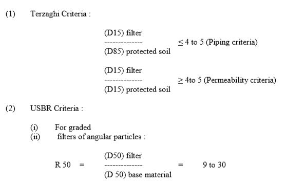

The above criteria takes into account only the grain size
of base material, and is based on
studies made with non-cohesive soils.
Even though the filters are provided generally to take
care of the seepage through the pores of
the embankment soils, they should
also be capable of preventing erosion of
soils through concentrated leaks that may occur in the dam body or at the
foundation contact.
Certain improvements and modifications to the above
criteria have been brought recently on the basis of controlled laboratory tests
performed by various organizations and individuals. Contributions by the US
Department of Agriculture, Soil Conservation Service is worth making a special
mention. Filter tests have been
conducted using compacted impervious soil specimens with an artificial slot or
hole and subjected o water flow discharging into the filters of varying coarseness. These studies confirmed that a conservative
filter would be remarkably effective in preventing erosion and sealing off
concentrated leaks, even with relatively high water pressures, velocities and
gradients. Such filters are required on
the downstream face of impervious core of a zoned embankment dam, and in the
chimney filter of a homogeneous dam section.
Because of the important role of these filters they are also known as
‘critical filters’. Some of the useful
conclusions drawn from the studies are :
i) The gradation curve of a filter need not have to be
parallel or similar in shape to the gradation curve of the base material.
ii) A filter should be uniformly graded to provide
permeability and prevent segregation.
Particles finer than 0.075 mm in the filter should not exceed 5 per cent
to ensure adequate permeability. The
permeability of a filter should be at least 25 times that of the base material
(D15F should be more than 5xD15B).
iii) Coarse broadly graded soils need finer filters than
believed to be necessary. The filter
should be designed to protect the fine matrix of the base material
rather than the total range of particle sizes. Filters designed based on minus 4.75mm are
found to be satisfactory.
iv) Sands and gravelly sands with average D15 size of 0.5
mm or smaller are conservative filters for most of the fine-grained clays
(including dispersive clays) in nature with D85 size of 0.03 mm or larger.
v) Sand filters with average D15 size of 0.1 mm or
smaller are conservative for the finest dispersive clays. Based on the above
findings, the US Interior Bureau of Reclamation (USBR) has developed a new set
of filter criteria (2). The filter
gradation limits are determined through steps A to B as described below:
A. Select the gradation curve of the base soil that requires
the smallest D15F size.
B. Proceed to step
D if the base soil does not contain gravel (4.75 mm and above).
C. Prepare adjusted gradation curves for soils with
particles larger than 4.75 mm. Use the
adjusted curve in working step D.
D. Determine the category of the soil from Table-1.
E. Determine the maximum D15F size in accordance with
Table-2.
F. To ensure sufficient permeability set the minimum D15F
size greater than or equal to 5xD15B, but not less than 0.1 mm.
G. Set the maximum particle size at 75 mm and the maximum
passing 0.074 mm must have a plasticity index of zero.
H. Design the filter limits within the maximum and
minimum values determined in steps E, F and G.
Plot the limit values and connect all the maximum and minimum points by straight
lines.
Typical filter gradation limits arrived for a category 2
type of base soil

ALSO READ: DESIGN PRINCIPLES OF EARTH DAM
No comments:
Post a Comment